Hi @adit,
I think there are a couple of distinct things to mention:
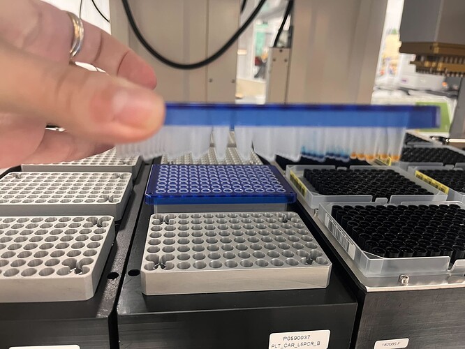
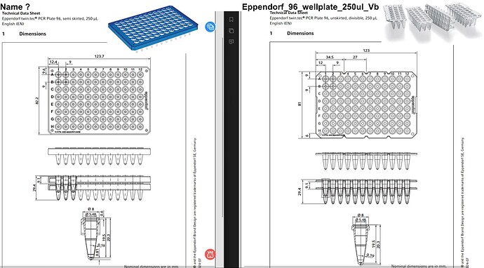
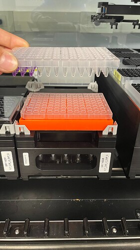
- The plate shown in your picture is not
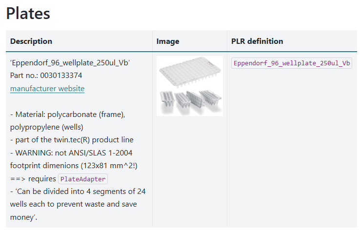
Eppendorf_96_wellplate_250ul_Vb:
Is different to the definition shown in the docs: Eppendorf — PyLabRobot documentation
i.e. you are working with a semi-skirted plate, while this definition is for a non-skirted plate that can be broken into 4 separate pieces.
I don’t know the plate you are using but it would be best to generate its definition and record its Eppendorf manufacturer part number inside the definition.
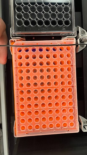
- As @rickwierenga mentioned, your situation is why I invented the PLR PlateAdapter class: this class physically represents the silver-grey block with holes in your image.
I have not yet gotten around to writing up a nice explainer in the docs, in the meantime you can read its definition and functionality in the PR Rick provided and the Python library file (pylabrobot/pylabrobot/resources/plate_adapter.py at main · PyLabRobot/pylabrobot · GitHub).
In short, the hole-grid of the plate_adapter and the well-grid of a plate need to be aligned. PlateAdapter automates the alignment process for us in the x and y dimensions. I.e. even though you might use very different plates (i.e. dx, dy could be vastly different) when these plates are placed on a PlateAdapter they automatically have the correct x-y coordinates.
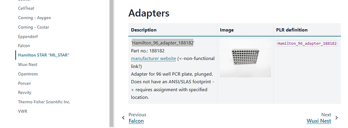
I have integrated the specific Hamilton PlateAdapter shown in your image as Hamilton_96_adapter_188182 (Hamilton STAR “ML_STAR” — PyLabRobot documentation)
- Deck assignment:
For your specialised carrier this is indeed a bit confusing. Do we have a PLR definition for PLT_CAR_L5PCR?
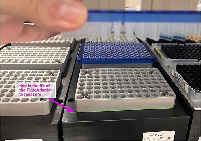
I am not familiar with this carrier but from your image it appears that this carrier does not have plate_holders/plate_sites but instead just has the Hamilton_96_adapter_188182 directly mounted onto the top plate of the carrier.
I would not be surprised if Hamilton’s GUI is abstracting all of this away by making the top of the adapters the plate_holder/plate_site in its definitions… which then would require painful manual declaration of specific plates onto it.
My recommendation to solve this quickly:
Step 1: define a PLT_CAR_L5PCR in your script and assign it to a deck.
Step 2: measure the front-left-bottom position of the physical Hamilton_96_adapter_188182 instances; store their 5 values.
Step 3: create 5 digital PLR instances of Hamilton_96_adapter_188182 and assign them to the PLT_CAR_L5PCR with the measured location values.
Now you can immediately use the Hamilton_96_adapter_188182 and add your semi-skirted plates on them.
Note: This carrier seems to be standard configured like this? If so we should probably just update its definition to what you figure out in steps 1, 2, 3. Then you only have to measure this accurately once and everyone around the world will be able to use it forever 
- Nuance about a
PlateAdapter’s plate_z_offset
Different plate_adapters will have differently shaped holes, and different wells will have different shapes too.
As a result, the different wellplates will have a different “plate_z_offset” that has to be empirically determined for each plate_adapter-wellplate combination.
You simply modify this value with Hamilton_96_adapter_188182_instance.plate_z_offset = 3.2 at runtime if you find that an offset of 3.2mm is what places the well_cavity_bottom digitally to the the corresponding physical position.
There is a lot going on, so please don’t hesitate to ask more questions.
