TipRacks are one of the last resources which we have not discussed or revised after my initial implementation. That means how it is currently implemented models VENUS somewhat closely. There are some issues with this (see below).
Current implementation
In the current implementation, Tips aren’t resources. Their pickup and drop-off location is determined by the TipSpot, a location in the TipRack.
The z-location of the TipSpots is below the “surface-level” of the rack (not counting the border), at a different height depending on which tip rack is used. This is dz in a hamilton tip rack.
Limitations/issues
~In PLR, you can only pick up multiple tips of the same kind in a single command currently. the firmware api supports different tip types on each channel~ (not true)
While possible, it is a little bit non-obvious how to store tips of different tips in the same Rack
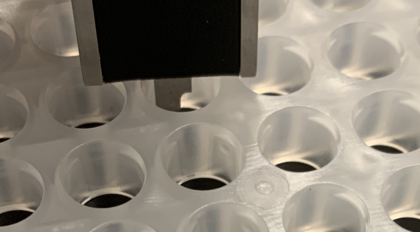
TipRack.get_highest_known_point doesn’t take into account the height of the tip above the tip rack (the collar that sticks out)
TipRacks don’t sink into the ResourceHolder (fka CarrierSite) in our model, even though they do physically. Related, the z=0 of a tip rack is not the actual rack bottom
Physical reality / what we should do
The tip racks, the plastic holders, are actually the same for every pip-tip type. Only the sticker is different.
→ we should have a singular definition for this piece.
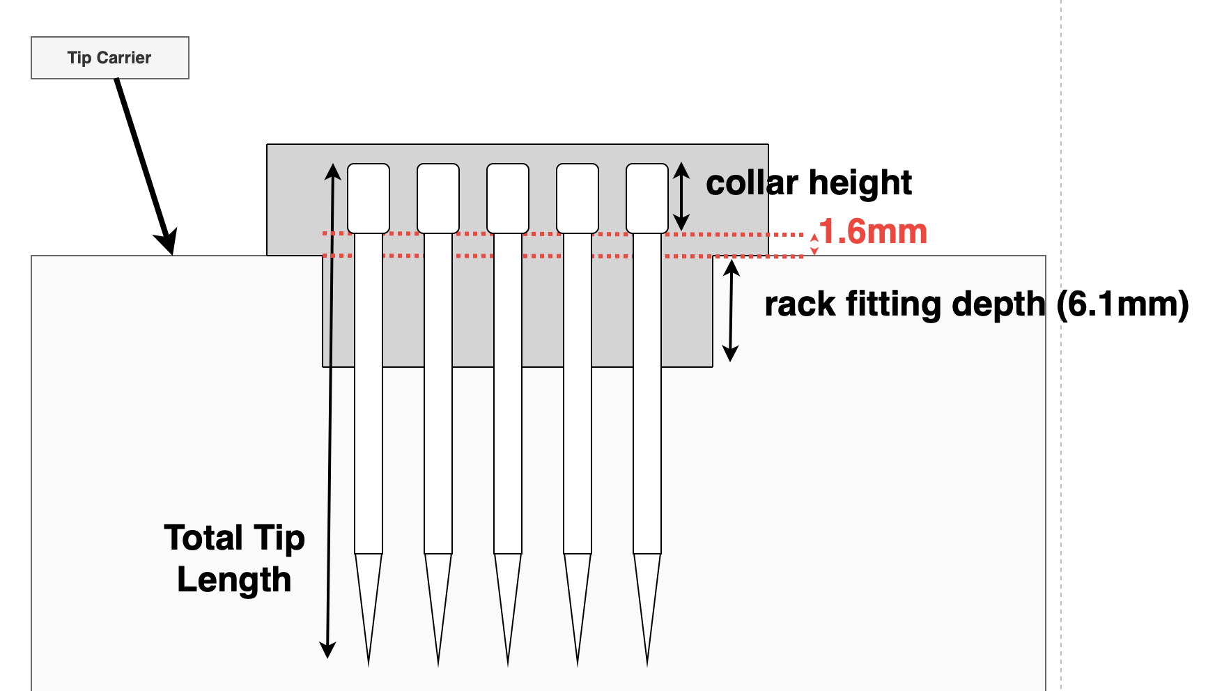
→ each tip has a ‘collar height’, which we can use to determine the bottom of the tip. The tip sits at total_tip_length - collar_height - hole_height below the tip rack.
Thank you @rickwierenga , nice writeup with many details regarding the geometry.
Actually there are also Nested Tip Racks. But I agree, there are basically just “normal” tipracks and nested tip racks and both are used for different types of tips.
What prevents us from defining the TipSpot at the z-hight where the collar will sit in the tiprack? This would simplify (obsolete) the pickup height calculation.
they can be separate tip rack definitions, using the same tips. I believe @CamilloMoschner is working on this
Yes, we should have tip spots at the correct location (their lfb). I see the TipSpots as the holes in a tip rack. Currently, it’s wrong because some tip spots are modeled below the tip rack (so that tip sit at the bottom of the spot). With the new approach, tips will sit below (z < 0) TipSpots.
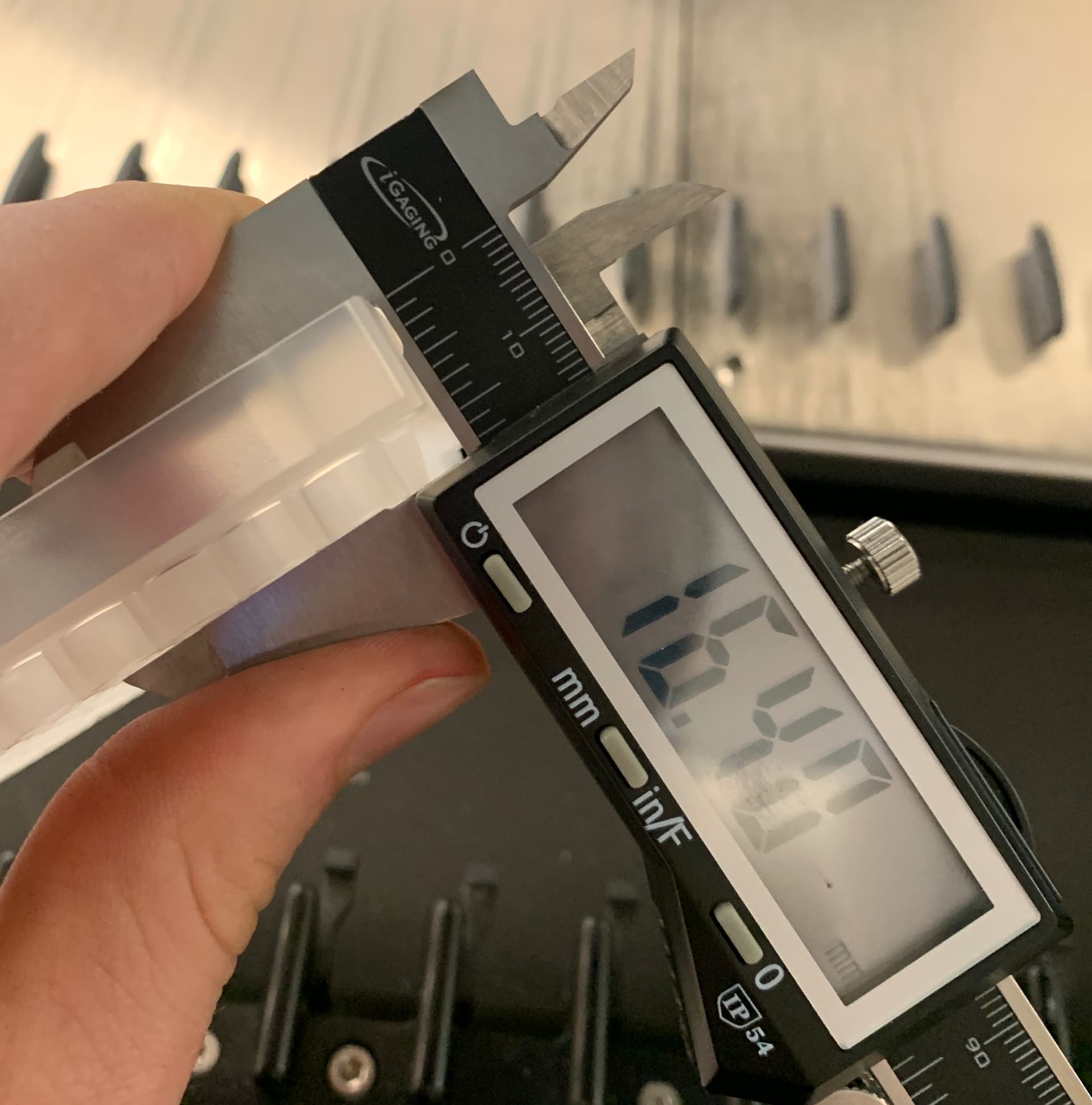
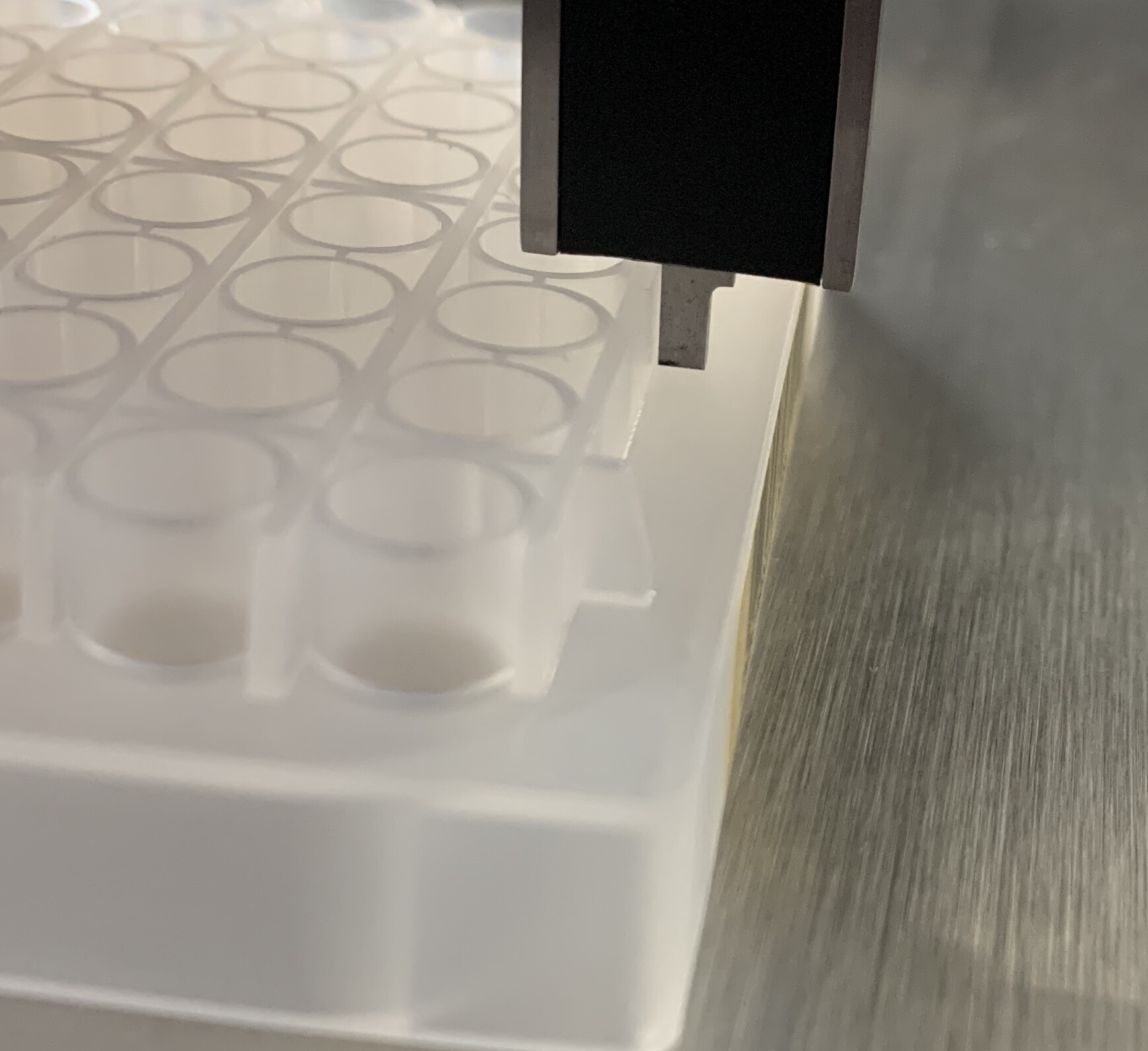
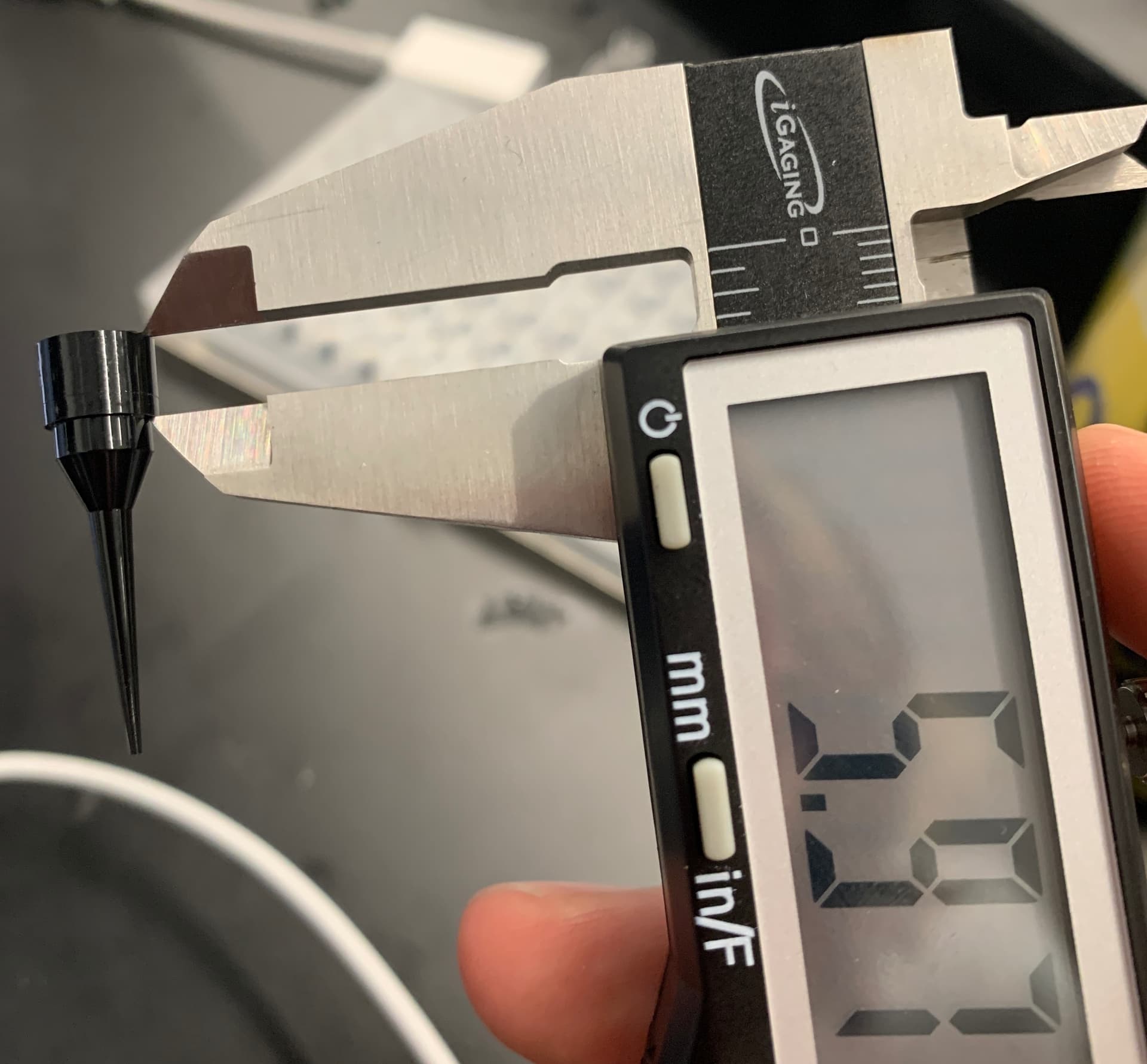
correction from post above: the resource holder sinks by 6.1mm, not 5.9. I measured it incorrectly before. The total height of the hole (“TipSpot”) that overlaps with the tip is 7.7mm.
The tip pickup command on STAR (C0TP) has two primary parameters:
tp: begin_tip_pick_up_process
tz: end_tip_pick_up_process
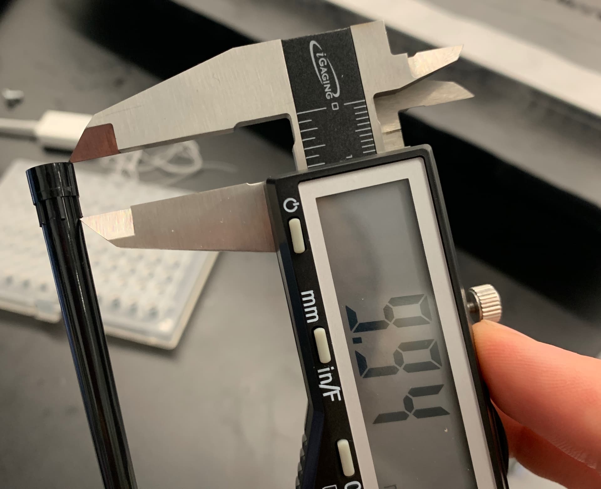
For every tip pickup, tz is 1.6mm above the tip carrier top, or 1.6+6.1 = 7.7mm above the tip rack bottom. The collar height determines the paramter tp, which is where the pip channels move down slowly. (This parameter can actually be as small as 1.7mm above tz with normal high volume filter tips. turbo mode for pickup )
With what I proposed above:
Define tip racks location.z to be tip_carrier.size_z -6.1
Measure collar height for known tips (this information is not available in venus I think, but believe we have all hamilton tips at retro)
set tz to rack height + 7.7, tp to rack height + 7.7 + collar height
TipSpot z is 0 wrt tip rack, height is 7.7
thoughts? c @CamilloMoschner. @ben does this have sufficient parameters for using the chinese tips?
I agree, this means the new TipRack class must store this information.
I agree, the new Tip class must store this information
I think we should model each component here separately according to physical reality:
e.g.: for a MFX TipHolder
Deck: top_z = 100 mm
MFX carrier: top_z = 118 mm
MFX TipHolder: top_z: = 214.8 mm
TipSpot: z = 216.4 mm
The most important part here is the TipSpot because it is the tz in single-channel pickups and za in 96-head pickups.
That way these synonymous parameters reflect a real physical entity that we can let the STAR accurately measure via ztouch-probing.
No, not quite: the TipRack is actually very similar to wellplates in that it can have a skirt (plate) or a wall (TipRack) and a 2D grid of holes (Wells → Plate / TipSpot → TipRack).
Accordingly I propose that TipSpot is still defined based on a dx, dy, and dz relative to their parent, the TipRack.
The dz value thereby becomes the thickness of the holes - the TipSpot becomes the orifice / opening at the top of the hole.
I have not been able to figure everything out yet and would like to ask for feedback on this proposal:
Major overhaul of the Tip / TipSpot / TipRack resource management system
I believe any meaningful change to any of these 3 classes will require corresponding changes in the others.
First, stepping backwards, what are the types of TipRacks we are usually dealing with?
I would say there are 2 geometrically and behaviourally different ones:
The EmbeddedTipRack - this is what some might call a “standard” TipRack; they cannot stand on their own, they require a TipHolder at all times to be functional. The EmbdeddedTipRack is geometrically defined by an x-z or y-z cross-section in which the bottom part is narrower than the top part:
→ we have not yet modelled a resource like this accurately in PLR!
The difficulty lies in the fact that the TipHolder opening is actually narrower in both the x- and y-dimension compared to the TipRack.
This mean: we have to assign the EmbeddedTipRack based on the TipHolder’s and EmbeddedTipRack’s center-center position in the x- and y-dimension and the “top” of TipHolder.size_z - EmbeddedTiprack.rack_fitting_depth in the z-coordinate.
→ this then accurately models how the EmbeddedTipRack “embeds” into the TipHolder, giving it the descriptive name.
The NestedTipRack - actually a misnomer (by Hamilton ) because EmbeddedTipRacks can also be nested! (and even in VENUS a “stacking height” is defined for EmbeddedTiprack!) - maybe they should be called StandingTipRack (??)
It’s defining geometric characteristic is that it is completely self-sufficient and does not require a separate TipHolder to embed into. (important information for robotic arms to resupply the deck with off-deck stored tip_racks)
Instead it can just sit on a normal ResourceHolder.
Furthermore, an EmbeddedTipRack can - but does not have to - have its TipSpots on the very top of the rack but a StandingTipRack is (almost) always expected to have its TipSpots on the very top.
With TipSpot being defined this way, we can update our current Tip definition:
instead of the current way of having it Tip sit on the TipSpot (i.e. the TipSpot is underneath the EmbeddedTipRack) → TipSpotis the orifice of the tip_rack and every Tip must have a Tip.collar_size_z attribute - which is then used to assign the Tip into its accurate origin position.
crucially, EmbeddedTipRack and StandingTipRack then become standalone resources like everything else - meaning… in the Hamilton universe we only have to maintain two (!) tip_racks (ignoring 384_tip_racks, 4mL_tip_racks, and 5mL_tip_racks for the moment).
This then models the physical reality modularity of these two TipRacks
But PLR is not a Hamilton SDK but a lab automation SDK.
These changes are aimed at enabling powerful usage of i.a. …
StandingTipRacks (automated tip pickup / drop calculation at runtime)
the Hamilton “elevated TipRack adapter” i.e. an EmbeddedTipRack without walls that empowers partial 96-head tip pickups - massively accelerated tip sorting algorithms and simplifying PLR-empowered throughput adaptive protocol writing
further down the line (with the updates to Tip and ChannelHeadTool) usage of non-standard channel_head_tools like the lid_suction_tool and diy-made tools
The regular tip blisters are not great since you can’t reseal them properly. These are definitely used in any cell culture environments. I’ve never seen the embedded ones you’ve linked.
If you use the ones without a filter, yes - according to VENUS the stacking height is 15.5 mm in that case
I generally agree that not all StandingTipRacks have to be able to be nestable… but I cannot think of an immediate example that cannot - Opentrons ones can:
In regards to their parent - the TipHolder - the TipSpots would be in relationship to the TipHolders flb.
Physically speaking the z-coordinate that matters is the top opening of the hole though (i.e. that is tz / za) and can be easily measured.
ease of measurement: either way you have to caliper the height/depth (size_z) of the hole. the difference is whether we actually model its height and set dz = 0 or make its height 0 and assign dz to what would otherwise be the height
Just because they have a listed stack height I wouldn’t say it’s possible. Have you done this?? The stack height might be for the Vantage with the under the deck tip holders… or they added a stack height for who knows what reason. I cannot imagine the iswap could move these since they are so flimsy, or that a tip pickup of them stacked would work, but I could be wrong.
No, maybe I am still trusting VENUS more than it deserves
I’ll try tomorrow - based on the geometry it should be possible, but because the tipracks don’t nest into one another - only the tips would - I can imagine it being very flimsy; but would that be good enough for robotic precision when briefly storing or prepping them for transport?
Interesting, I have never used a VANTAGE but I thought the underdeck tipracks where all StandingTipRacks/NestedTipRacks?
A ResourceHolder subclass dedicated to taking TipRacks as children:
The TipHolder ensures that the EmbeddedTipRack’s center-center aligns with its own center-center + asserts that the its hole is smaller than the EmbdeddedTiprRack’s size_x and size_y (if it was bigger the tip_rack would just fall through).
That is required becauseResourceHolder does not keep information about the size of the site that the incoming tip_rack will go to + the surface on which the tip_rack sits on is completely flat, i.e. there is no dedicated child_location → that means we need a resource that moves the flb of the EmbeddedTipRack into the right location based on the size of the tip_rack + its center-center + the TipHolder’s site’s center-center.
I think it sounds a lot more complicated than it is
It is actually quite similar to when I created the PlateAdapter, though that was more difficult because every PlateAdapter has to align the well_grid of an incoming wellplate to the hole_grid of the PlateAdapter based on the wellplate’s dx & dy and the PlateAdapter’s holes’dx & dy; here we only have to align the two centers.
Now that I read it again - it should really be called TipRackHolder ?